This is the second part of a series of posts detailing my adventurous venture into the world of hardware hacking/tweaking, whatever you call it. Part 1 has a full introduction.
The Touch Sensor
 |
| The touch sensor |
So, following my half-successful attempt at getting the stepper motors to work, I decided to focus on something simpler: the touch sensor. At first I thought that this sensor would be a complex series of variable resistors, giving an analog output in terms of how much pressure was being exerted or how far the pin had been pushed in, so I decided against plugging in stuff and seeing what came out for fear of ruining the component.
The teacher who set me this task of tweaking the sensors told me briefly, that the NXT platform was open source and that the schematics could be found online. Having remembered this useful fact, I scoured the Lego Mindstoms NXT website to find these. Buried deep within the “advanced users” section, I found the Hardware Development Kit, along with a whole bunch of other useful stuff, like the Bluetooth API and software development kits, both of which I would have absolutely no idea what to do with!
Looking through the schematics of the complex processor and other sensors, I felt that the touch sensor could not get any better! Then, after opening the schematics file for the touch sensor, I was greeted with this friendly image, lost in the white of the A3-sized document:
 |
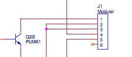
| The Lego touch sensor schematic |
It was nothing more than a simple push-to-make switch! Fantastic! I immediately went to work wiring the thing up to my Arduino, connecting pin 1 to +5v, pin 2 to 0v through a 10kΩ resistor and pin 3 to the digital I/O pin 2 on the Arduino, as shown in the image below.
 |
| Schematic of touch sensor hook-up. Image developed using Fritzing. |
Using the following Arduino sketch, I was easily able to use the sensor.
/*
This is a program to test the Lego NXT Touch Sensor.
A schematic of the circuit required can be found on TheCompBlog.com.
This code was writen (badly) by Nicolas Weninger, author of TheCompBlog.com.

THIS SOFTWARE COMES WITHOUT ANY WARRANTY, IMPLIED OR EXPLICIT, TO THE MAXIMUM EXTENT PERMITTABLE BY LAW. THIS INCLUDES
WARRANTY AGAINST DAMAGE TO COMPUTER SYSTEMS OR DATA, LOSS OF PROFIT, PERSONAL INJURY OR DEATH.

This code is in the public domain.
*/

const int button = 2; //connects to pin3 of the sensor

void setup()
{
  Serial.begin(9600);
  pinMode(13, OUTPUT);
}

void loop()
{
  if(digitalRead(button) == 1)
  {
    digitalWrite(13, HIGH);
  }
  else
  {
    digitalWrite(13, LOW);
  }
  Serial.println(digitalRead(button));
}
However, I came to the realisation that the actual processing unit of the NXT does not have a resistor connected to pin 3 of any of the input ports, meaning that, like the Arduino, the processing unit must have some sort of software-activated pull-up or pull-down resistor, activated when told that the touch sensor would be connected to that port, steering the input signal either high or low unless the button was pressed. As the Arduino has built in software-activated pull-up resistors, I decided to try my hand at wiring the sensor up without any external circuitry.
It was a relatively simple endeavour. One would only have to alter the ‘if’ statement in the code to reflect the fact that the button sends a low, not a high, signal to the board.
 |
| Without an external resistor. Image developed using Fritzing. |
/*
This is a program to test the Lego NXT Touch Sensor.
A schematic of the circuit required can be found on TheCompBlog.com.
This code was writen (badly) by Nicolas Weninger, author of TheCompBlog.com.

THIS SOFTWARE COMES WITHOUT ANY WARRANTY, IMPLIED OR EXPLICIT, TO THE MAXIMUM EXTENT PERMITTABLE BY LAW. THIS INCLUDES
WARRANTY AGAINST DAMAGE TO COMPUTER SYSTEMS OR DATA, LOSS OF PROFIT, PERSONAL INJURY OR DEATH.

This code is in the public domain.
*/

const int button = 3; //connects to pin1 of the sensor

void setup()
{
  Serial.begin(9600);
  pinMode(button, INPUT);
  pinMode(13, OUTPUT);
  digitalWrite(button, HIGH); //turns on the 20KΩ pull-up resistor
}

void loop()
{
  if(digitalRead(button) == 0)
  {
    digitalWrite(13, HIGH);
    Serial.println("1");
  }
  else
  {
    Serial.println("0");
    digitalWrite(13, LOW);
  }
}
The Light Sensor
 |
| The light sensor |
The light sensor is an active sensor, so I was under the impression that I would have to do some advanced clocking [is that the right word?] stuff. Looking at the documentation on this sensor in the Lego hardware developer kit, it did not seem too complicated. I proceeded to wire up the sensor, with pin 1 to an analog input, pins 2 and 3 to ground, 4 to +5V and 5 to a digital output to control the on-board LED. A simple Arduino sketch later, I was reading a whole bunch of 1s, 2s and 0s on the analog input. For those of you who want clarification, although 1 might represent a ‘high’ voltage and 0, ‘low’, the analog pin on the Arduino reads a voltage, not a signal, and compares that to 5V or whatever may be connected to the AREF pin. Through the ADC, it converts this value to a number between 0 and 1023. The fact that the ADC was spitting out 0s and 2s indicated that there was almost no voltage present at the pin.
As one would do in this situation, I turned to Google for help (or Bing; whatever floats your boat). Five pages of search results returned no valuable information, as did trawling through all the forums I could find. Unusually for me, I posted a new topic on the Arduino Forum out of desperation, not expecting to get a response before the next week. Interestingly, a very helpful member responded within an hour. It was evident from his response that he had spent a decent amount of time troubleshooting the problem, having looked at the Wikipedia page for the NXT connectors and the circuit schematics in the Lego hardware development kit. He then proceeded to inform me on how to fix the problem. One of the problems I had failed to notice was the fact that pin 1 was an open-collector of a transistor, making it similar to the simple common-emitter circuit we had studied in my technology lessons. These require a pull-up resistor (a resistor connected to the supply voltage or relevant high voltage rail) to create the voltage drop, creating the analog signal.
 |
| The open-collector |
I coded up another fun addition, namely, a push-button latch for the on-board LED in the sensor. I presume this LED was added to supply light when not enough ambient light was present. In terms of which resistor to use as deribed above, an external 10kΩ one proved to give more stable signals than the on-board 20kΩ pull-up resistors on the Arduino board. Experiment with different resistor values and see what happens. I was limited to my supply of 330Ω, 1KΩ and 10KΩ resistors.
The code and schematic are included below.
 |
| Image developed using Fritzing. |
/*
This is a program to test the Lego NXT Light Sensor.
A schematic of the circuit required can be found on TheCompBlog.com.
This code was writen (badly) by Nicolas Weninger, author of TheCompBlog.com.

THIS SOFTWARE COMES WITHOUT ANY WARRANTY, IMPLIED OR EXPLICIT, TO THE MAXIMUM EXTENT PERMITTABLE BY LAW. THIS INCLUDES
WARRANTY AGAINST DAMAGE TO COMPUTER SYSTEMS OR DATA, LOSS OF PROFIT, PERSONAL INJURY OR DEATH.

This code is in the public domain.
*/

const int reader = A5; //connects to pin1 of sensor
const int button = 2; //momentary switch
const int light = 3; //connects to pin5 of sensor

int state = LOW;
int previous = LOW;

void setup()
{
  Serial.begin(9600);
  pinMode(light, OUTPUT);
}

void loop()
{
  int reading = digitalRead(button);
  if(reading == HIGH && previous == LOW)
  {
    if(state == HIGH)
    {
      state = LOW;
    }
    else
    {
      state = HIGH;
    }
  }

  digitalWrite(light, state);
  previous = reading;
  Serial.println(analogRead(reader)); //print the light level reading
  delay(10); //good practice after an analogRead. Don't know why though…
}
In part 3, I shall be talking about the ultrasonic rangefinder and the colour sensor, the more interesting and challenging ones! I am almost there with the former, just some tweaking required.
In the case that I do not get the latter finished by then, I will update you on my progress with the motors. I have ordered the NXT shield, as decried in part 1, and am going to solder it together next week.